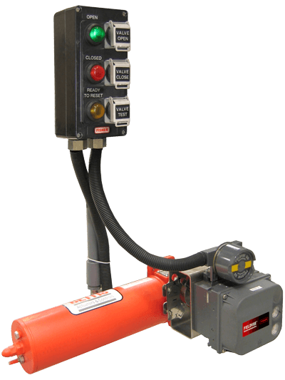
For process manufacturers and producers with safety shutdown applications, local control panels are often installed to provide visibility and control actions to operators locally out in the process area. Actions can be taken at these panels to initiate an emergency shutdown.
I caught up with Emerson’s Riyaz Ali about how these local control panels work with safety shutdown valves (SSVs) and the digital valve controllers (DVCs) that control them. He described the Fisher LCP100 local control panel working with the FieldVue DVC6200 SIS digital valve controller and Bettis valve actuator. These local control panels (LCPs) have three lights (RED, GREEN, AMBER) and three push buttons. The lights indicate the status of the SSV. A solid green light indicates that the valve is open and the signal from the safety instrumented system’s (SIS) logic solver is normal.
A solid red light indicates that the valve is closed and that the SIS has sent a shutdown (trip) signal. A solid amber light indicates that the valve is latched in the closed position, but ready to be opened. If the red or green light is flashing, then the valve is traveling to either the open or closed position.
The three buttons are used to manually operate the SSV. The “valve open” button, next to the green light, moves the valve to its normal operating position. The “valve close” button, next to the red light, trips the valve to its shutdown, closed state. The valve test button, next to the amber light, initiates a partial stroke test configured in the DVC6200 SIS.
Riyaz shared with me that during the LCP100 design stage, a conscious decision was taken based on discussions with major customers on the number of push buttons and lights, display of lights, color code, lamp specs, etc. Coming from these discussions was a design requirement to minimize the number of push buttons and lights. Colors were chosen based on oil & gas industry standards for color codes used for the operation of other critical assets such as pumps, motors, analyzers etc.
Riyaz has been asked whether or not additional lights are required on the local control panel. While he has heard of other panels with additional lights added, from a simplicity and ease of use perspective, the light colors are based on “NORMAL Healthy STATE” or “TRIPPED Demand STATE” for quick recognition and comparable to designs for pumps, motors and other critical machinery. To goal is fast recognition without confusion.
Additional diagnostics through the light come via blink patterns. During NORMAL state, if the valve travels to other positions, the solid GREEN light will flicker slowly. During a partial stroke test, if the valve moves to desire travel, then the solid GREEN light will flicker. Upon completion of the partial stroke test, if the valve did not pass the test, the solid GREEN light will flicker slowly. During a safety trip state, if the valve goes to FAIL SAFE STATE, the RED light will flicker. After this trip condition, if the valve does reach FAIL SAFE STATE, the RED light will become solid.
Riyaz emphasizes that most of the process manufacturers and producers with whom he’s interacted have adopted a philosophy to use the flicker of lights as a diagnostic in cases of issues with LCP or DVC rather than additional hardware.
If you’ll be attending the October 24-28 Emerson Exchange conference here in Austin, make sure to add the Fisher FIELDVUE Instruments Update and the FIELDVUE Digital Valve Controller using ValveLink blended learning course to your schedule. You can also connect and interact with other safety valve experts in Valves group in the Emerson Exchange 365 community.

